Life, part 2
Code for this episode can be found here.
There are literally fifty years of articles explaining Conway's Game of Life, starting with the one that introduced it to me: the October 1970 issue of Scientific American. Seems like a great time to do one more! I'll go pretty quickly, since this is familiar to a lot of readers already.
Imagine an infinite flat board of square cells, like a huge piece of ordinary graph paper. Every cell has only two possible states, which we conveniently call alive" and dead".
Just as the space in which Life is played is divided into discrete portions, so too is time. In the Life universe every time the clock ticks", some cells may be born, some may continue to live, and some may die. The rules governing this evolution are straightforward:
- The neighbors" of a cell are the eight cells which surround it.
- If a cell is alive now and has exactly zero or one living neighbors, it dies of loneliness.
- If a cell is alive now and has exactly two or three living neighbors, it survives.
- If a cell is alive now and has four or more living neighbors, it dies from overcrowding.
- If a cell is dead now and has exactly three living neighbors, it becomes alive.
- If a cell is dead now and has any other number of living neighbors, it stays dead.
These rules can be simplified greatly; I leave it as an exercise to the reader to verify that these rules are the same:
- If a cell has exactly three living neighbors then it is alive on the next tick irrespective of whether it is currently alive or dead.
- Otherwise, if a cell is alive and has exactly two living neighbors then it is alive on the next tick.
- Otherwise, the cell is dead on the next tick.
Let's look at some simple examples:
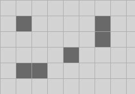
All of the living cells have one or no living neighbors, so they will all be dead on the next tick. Only one of the dead cells has exactly three living neighbors. On the next tick this will have a single living cell, and then on the tick after that they'll all be dead.
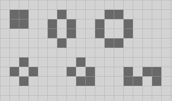
By contrast, these still lifes" have the property that every living cell has two or three living neighbors, but no dead cell has exactly three living neighbors. These still lifes are traditionally called the block, beehive, pond, tub, boat and snake; they are stable. There are many, many more stable structures like this.
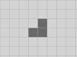
The easiest birth that leads to a stable configuration is this triomino:
I'm sure you see which dead cell has exactly three living neighbors; it will be alive in the next tick. All the live cells have two living neighbors, and no other dead cell has three, so this will turn into a block and then will be stable.
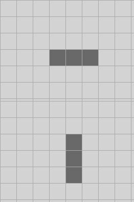
Can we come up with an oscillating pattern? It is not hard!
For obvious reasons this triomino is called blinker". There are a number of other relatively small configurations like this which oscillate with a period of two ticks.
I'll finish this introduction off with the most important simple pattern in Life, the glider:
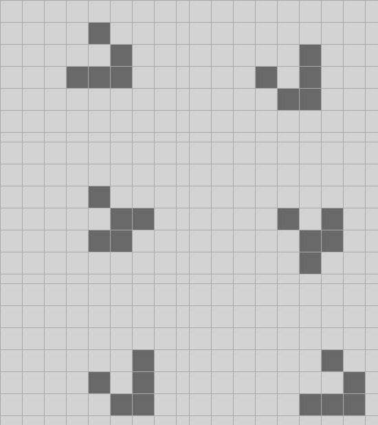
The glider oscillates between two basic forms, but after two ticks it has reflected itself along the diagonal axis, and then two ticks later it reflects back again to the original form, but offset by one cell east" and one cell south". The glider is the simplest spaceship" pattern; it is stable as it moves around the board. Here I've shown nine ticks in the life of a glider.
Clearly we can build gliders that move northeast, northwest and southwest easily enough, just by rotating the glider to point" another direction.
I want to look at some different techniques for simulating Life. As will become extremely apparent when you look at the code or run the executable, I almost never write the user interface portion of any software package; my entire career I've built semantic analyzers for programming languages and there's not a lot of UI design there. If I make foolish mistakes in my UI code, please feel free to point them out.
I'm therefore going to divide the project into a client form that has the user interface, that talks to a computation engine over an interface. I'll point out a few features of the client here and there, but mostly we'll concentrate on the computations.
As usual, I'll put the code on GitHub and I'll make a separate branch for each episode with new code. Sorry Mac users, it is a WinForms application.
The initial attempt here barely even has a user interface; it does not respond to user input except for the standard close, resize, and so on. But I've laid the groundwork for eventually implementing a more sophisticated client. In particular, a key problem to solve is identifying the rectangle of cells which is currently in view" in the UI and rendering those cells to the UI. I'd like to be able to zoom in and out.
We could implement arbitrarily scaled zooming, but as we'll see in later episodes, it's going to be convenient to restrict scaling to powers of two, and as I said, I'm interested more in the algorithms than a pleasant UI.
In order to achieve this, an important bit of form state is:
private int scale = -5;
The convention that I'm using here takes a moment to wrap your head around. The convention is:
- If the scale is zero, then every on-screen pixel represents exactly one Life cell. This is implemented in the client, but since there is no control surface yet, you'll have to adjust the scale in the debugger or recompile the code.
- If the scale is a negative number, then we are zoomed in". Each Life cell is represented by a square that is 1 << -scale pixels wide. By default, I've set the scale to -5, which means that each Life cell is represented by a 32 by 32 square of pixels. Again, you can tweak that up or down in the debugger.
- If the scale is a positive number then we go the other way: each pixel represents a square that is 1 << scale Life cells wide. This feature is not yet implemented, so don't bump the scale up into positive numbers just yet.
A lot of the code in the form is about translating from the pixel-based bitmap coordinates, where (0, 0) is the upper left corner; the x coordinate increases to the right, and the y coordinate increases as we go down. The Life grid is an infinite plane where each cell can be addressed by a pair of integers, so there is no corner"; I'm using the standard graph paper convention that the x coordinate increases to the right and the y coordinate increases as we go up. That entails some tricky bookkeeping, but we'll manage. I've configured the UI so that when it starts up, Life coordinate (-2, -2) is in the lower left corner of the picture box.
I've introduced my own immutable point and rectangle structs to represent regions of the Life grid. That's for three reasons. First, because the default point and rectangle structs are mutable, which gives me hives. Second, because they use integers, and I'm eventually going to be building Life grids that cannot be addressed by integers. And third, because as long-time readers of this blog know, I like to use the type system to find my mistakes before I make them. I'm not going to mix up LifePoint and Point easily!
The only other notable thing about the client is that it has a rarity; I've written unsafe code for something other than a compiler test case! That has happened only a handful of times in multiple decades of writing C# code. Setting individual pixels in a bitmap is slow and I'm going to be potentially setting a lot of them, so I've created a little function that parties directly on the raw bits of a bitmap in memory.
The interface between the client and the computation engine is straightforward; we'll be making it more complex in later episodes as we add features to the client:
interface ILife{ void Clear(); bool this[long x, long y] { get; set; } bool this[LifePoint v] { get; set; } void Draw(LifeRect rect, Action<LifePoint> setPixel); void Step();}This represents a mutable Life grid; long-time readers of my blog know that I prefer immutable data structures, and we'll look at how to represent an immutable Life grid efficiently in later episodes. Fortunately it is almost always easy to make a mutable implementation on top of an immutable one, but often not easy to go the other way.
The two indexers are just for convenience; they are semantically identical.
The Clear and Step methods should be straightforward; one clears the board of all living cells, and Step moves the board forward one tick. We'll add methods in later versions to move forward multiple steps.
The Draw method is the interesting one. Basically the idea here is that Life boards almost always have far more dead cells than alive cells because the overcrowding rule tends to keep the density low. We can therefore get a win by only drawing the live cells.
The convention for drawing is: the client passes in the rectangular region of the board that the client wishes to render, and the engine calls the callback for every live cell. In order to implement the zoom out" feature we'll make this method a little more sophisticated in future versions, so that the engine only calls back once per block of cells" that contains a live cell.
Next time on FAIC: We'll look at the naive implementation of the engine and discuss its time and memory performance.
