Letting Robocars See Around Corners

An autonomous car needs to do many things to make the grade, but without a doubt, sensing and understanding its environment are the most critical. A self-driving vehicle must track and identify many objects and targets, whether they're in clear view or hidden, whether the weather is fair or foul.
Today's radar alone is nowhere near good enough to handle the entire job-cameras and lidars are also needed. But if we could make the most of radar's particular strengths, we might dispense with at least some of those supplementary sensors.
Conventional cameras in stereo mode can indeed detect objects, gauge their distance, and estimate their speeds, but they don't have the accuracy required for fully autonomous driving. In addition, cameras do not work well at night, in fog, or in direct sunlight, and systems that use them are prone to being fooled by optical illusions. Laser scanning systems, or lidars, do supply their own illumination and thus are often superior to cameras in bad weather. Nonetheless, they can see only straight ahead, along a clear line of sight, and will therefore not be able to detect a car approaching an intersection while hidden from view by buildings or other obstacles.
Radar is worse than lidar in range accuracy and angular resolution-the smallest angle of arrival necessary between two distinct targets to resolve one from another. But we have devised a novel radar architecture that overcomes these deficiencies, making it much more effective in augmenting lidars and cameras.
Our proposed architecture employs what's called a sparse, wide-aperture multiband radar. The basic idea is to use a variety of frequencies, exploiting the particular properties of each one, to free the system from the vicissitudes of the weather and to see through and around corners. That system, in turn, employs advanced signal processing and sensor-fusion algorithms to produce an integrated representation of the environment.
We have experimentally verified the theoretical performance limits of our radar system-its range, angular resolution, and accuracy. Right now, we're building hardware for various automakers to evaluate, and recent road tests have been successful. We plan to conduct more elaborate tests to demonstrate around-the-corner sensing in early 2022.
Each frequency band has its strengths and weaknesses. The band at 77 gigahertz and below can pass through 1,000 meters of dense fog without losing more than a fraction of a decibel of signal strength. Contrast that with lidars and cameras, which lose 10 to 15 decibels in just 50 meters of such fog.
Rain, however, is another story. Even light showers will attenuate 77-GHz radar as much as they would lidar. No problem, you might think-just go to lower frequencies. Rain is, after all, transparent to radar at, say, 1 GHz or below.
This works, but you want the high bands as well, because the low bands provide poorer range and angular resolution. Although you can't necessarily equate high frequency with a narrow beam, you can use an antenna array, or highly directive antenna, to project the millimeter-long waves in the higher bands in a narrow beam, like a laser. This means that this radar can compete with lidar systems, although it would still suffer from the same inability to see outside a line of sight.
For an antenna of given size-that is, of a given array aperture-the angular resolution of the beam is inversely proportional to the frequency of operation. Similarly, to achieve a given angular resolution, the required frequency is inversely proportional to the antenna size. So to achieve some desired angular resolution from a radar system at relatively low UHF frequencies (0.3 to 1 GHz), for example, you'd need an antenna array tens of times as large as the one you'd need for a radar operating in the K (18- to 27-GHz) or W (75- to 110-GHz) bands.
Even though lower frequencies don't help much with resolution, they bring other advantages. Electromagnetic waves tend to diffract at sharp edges; when they encounter curved surfaces, they can diffract right around them as creeping" waves. These effects are too weak to be effective at the higher frequencies of the K band and, especially, the W band, but they can be substantial in the UHF and C (4- to 8-GHz) bands. This diffraction behavior, together with lower penetration loss, allows such radars to detect objects around a corner.
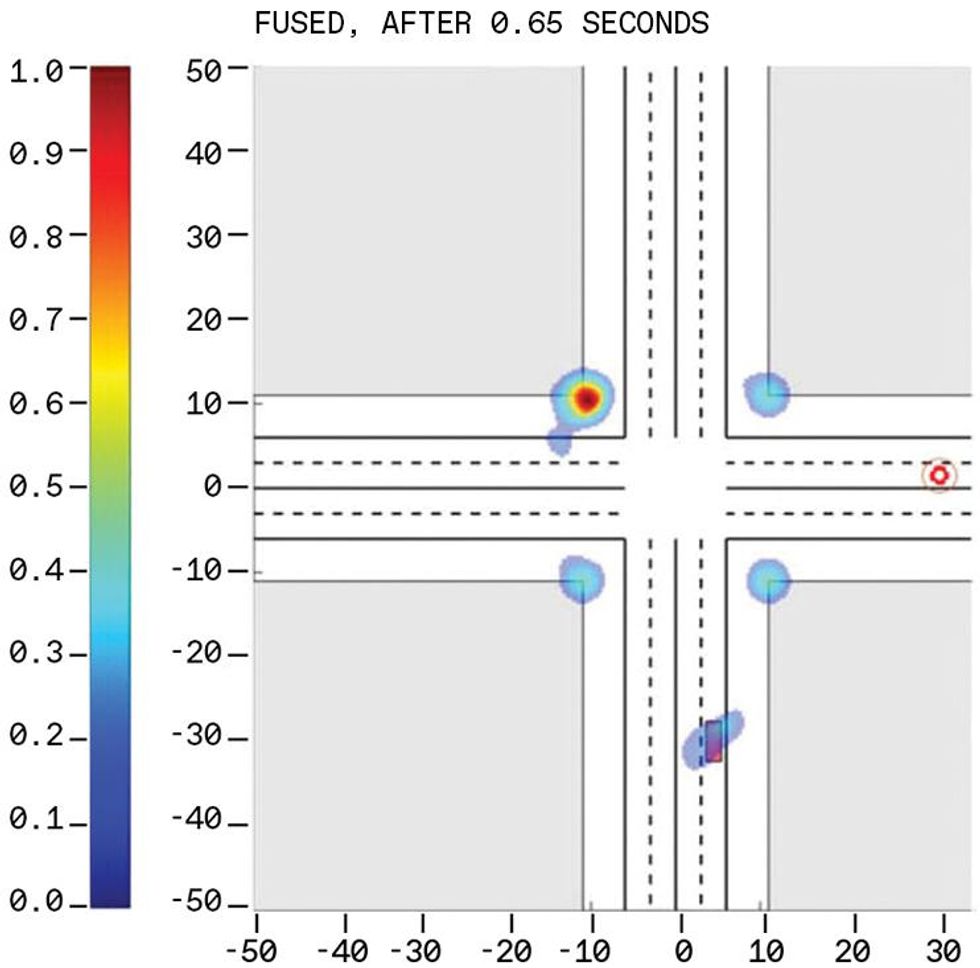
One weakness of radar is that it follows many paths, bouncing off innumerable objects, on its way to and from the object being tracked. These radar returns are further complicated by the presence of many other automotive radars on the road. But the tangle also brings a strength: The widely ranging ricochets can provide a computer with information about what's going on in places that a beam projected along the line of sight can't reach-for instance, revealing cross traffic that is obscured from direct detection.
To see far and in detail-to see sideways and even directly through obstacles-is a promise that radar has not yet fully realized. No one radar band can do it all, but a system that can operate simultaneously at multiple frequency bands can come very close. For instance, high-frequency bands, such as K and W, can provide high resolution and can accurately estimate the location and speed of targets. But they can't penetrate the walls of buildings or see around corners; what's more, they are vulnerable to heavy rain, fog, and dust.
Lower frequency bands, such as UHF and C, are much less vulnerable to these problems, but they require larger antenna elements and have less available bandwidth, which reduces range resolution-the ability to distinguish two objects of similar bearing but different ranges. These lower bands also require a large aperture for a given angular resolution. By putting together these disparate bands, we can balance the vulnerabilities of one band with the strengths of the others.
Different targets pose different challenges for our multiband solution. The front of a car presents a smaller radar cross section-or effective reflectivity-to the UHF band than to the C and K bands. This means that an approaching car will be easier to detect using the C and K bands. Further, a pedestrian's cross section exhibits much less variation with respect to changes in his or her orientation and gait in the UHF band than it does in the C and K bands. This means that people will be easier to detect with UHF radar.
Furthermore, the radar cross section of an object decreases when there is water on the scatterer's surface. This diminishes the radar reflections measured in the C and K bands, although this phenomenon does not notably affect UHF radars.
The tangled return paths of radar are also a strength because they can provide a computer with information about what's going on sideways-for instance, in cross traffic that is obscured from direct inspection.
Another important difference arises from the fact that a signal of a lower frequency can penetrate walls and pass through buildings, whereas higher frequencies cannot. Consider, for example, a 30-centimeter-thick concrete wall. The ability of a radar wave to pass through the wall, rather than reflect off of it, is a function of the wavelength, the polarization of the incident field, and the angle of incidence. For the UHF band, the transmission coefficient is around -6.5 dB over a large range of incident angles. For the C and K bands, that value falls to -35 dB and -150 dB, respectively, meaning that very little energy can make it through.
A radar's angular resolution, as we noted earlier, is proportional to the wavelength used; but it is also inversely proportional to the width of the aperture-or, for a linear array of antennas, to the physical length of the array. This is one reason why millimeter waves, such as the W and K bands, may work well for autonomous driving. A commercial radar unit based on two 77-GHz transceivers, with an aperture of 6 cm, gives you about 2.5 degrees of angular resolution, more than an order of magnitude worse than a typical lidar system, and too little for autonomous driving. Achieving lidar-standard resolution at 77 GHz requires a much wider aperture-1.2 meters, say, about the width of a car.
Besides range and angular resolution, a car's radar system must also keep track of a lot of targets, sometimes hundreds of them at once. It can be difficult to distinguish targets by range if their range to the car varies by just a few meters. And for any given range, a uniform linear array-one whose transmitting and receiving elements are spaced equidistantly-can distinguish only as many targets as the number of antennas it has. In cluttered environments where there may be a multitude of targets, this might seem to indicate the need for hundreds of such transmitters and receivers, a problem made worse by the need for a very large aperture. That much hardware would be costly.
One way to circumvent the problem is to use an array in which the elements are placed at only a few of the positions they normally occupy. If we design such a sparse" array carefully, so that each mutual geometrical distance is unique, we can make it behave as well as the nonsparse, full-size array. For instance, if we begin with a 1.2-meter-aperture radar operating at the K band and put in an appropriately designed sparse array having just 12 transmitting and 16 receiving elements, it would behave like a standard array having 192 elements. The reason is that a carefully designed sparse array can have up to 12 * 16, or 192, pairwise distances between each transmitter and receiver. Using 12 different signal transmissions, the 16 receive antennas will receive 192 signals. Because of the unique pairwise distance between each transmit/receive pair, the resulting 192 received signals can be made to behave as if they were received by a 192-element, nonsparse array. Thus, a sparse array allows one to trade off time for space-that is, signal transmissions with antenna elements.
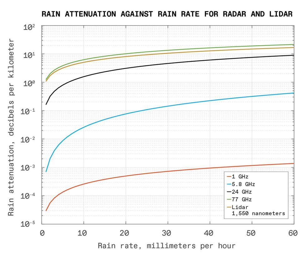 Seeing in the rain is generally much easier for radar than for light-based sensors, notably lidar. At relatively low frequencies, a radar signal's loss of strength is orders of magnitude lower.Neural Propulsion Systems
In principle, separate radar units placed along an imaginary array on a car should operate as a single phased-array unit of larger aperture. However, this scheme would require the joint transmission of every transmit antenna of the separate subarrays, as well as the joint processing of the data collected by every antenna element of the combined subarrays, which in turn would require that the phases of all subarray units be perfectly synchronized.
None of this is easy. But even if it could be implemented, the performance of such a perfectly synchronized distributed radar would still fall well short of that of a carefully designed, fully integrated, wide-aperture sparse array.
Consider two radar systems at 77 GHz, each with an aperture length of 1.2 meters and with 12 transmit and 16 receive elements. The first is a carefully designed sparse array; the second places two 14-element standard arrays on the extreme sides of the aperture. Both systems have the same aperture and the same number of antenna elements. But while the integrated sparse design performs equally well no matter where it scans, the divided version has trouble looking straight ahead, from the front of the array. That's because the two clumps of antennas are widely separated, producing a blind spot in the center.
In the widely separated scenario, we assume two cases. In the first, the two standard radar arrays at either end of a divided system are somehow perfectly synchronized. This arrangement fails to detect objects 45 percent of the time. In the second case, we assume that each array operates independently and that the objects they've each independently detected are then fused. This arrangement fails almost 60 percent of the time. In contrast, the carefully designed sparse array has only a negligible chance of failure.
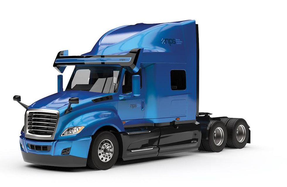
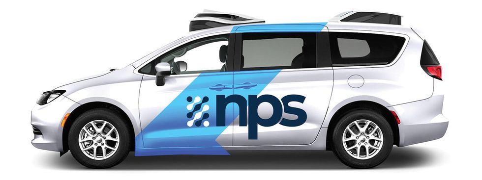 The truck and the car are fitted with wide-aperture multiband radar from Neural Propulsion Systems, the authors' company. Note the very wide antenna above the windshield of the truck.Neural Propulsion Systems
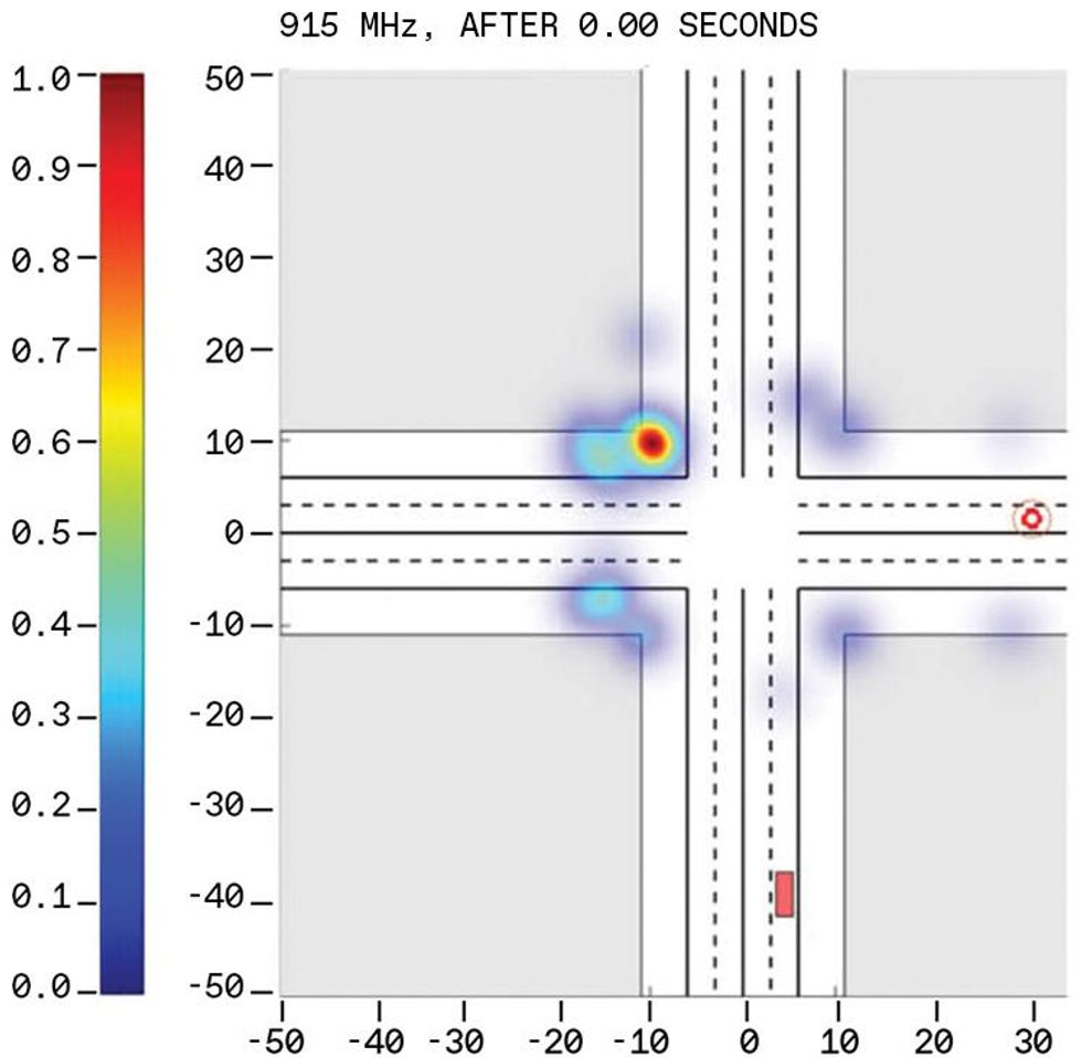
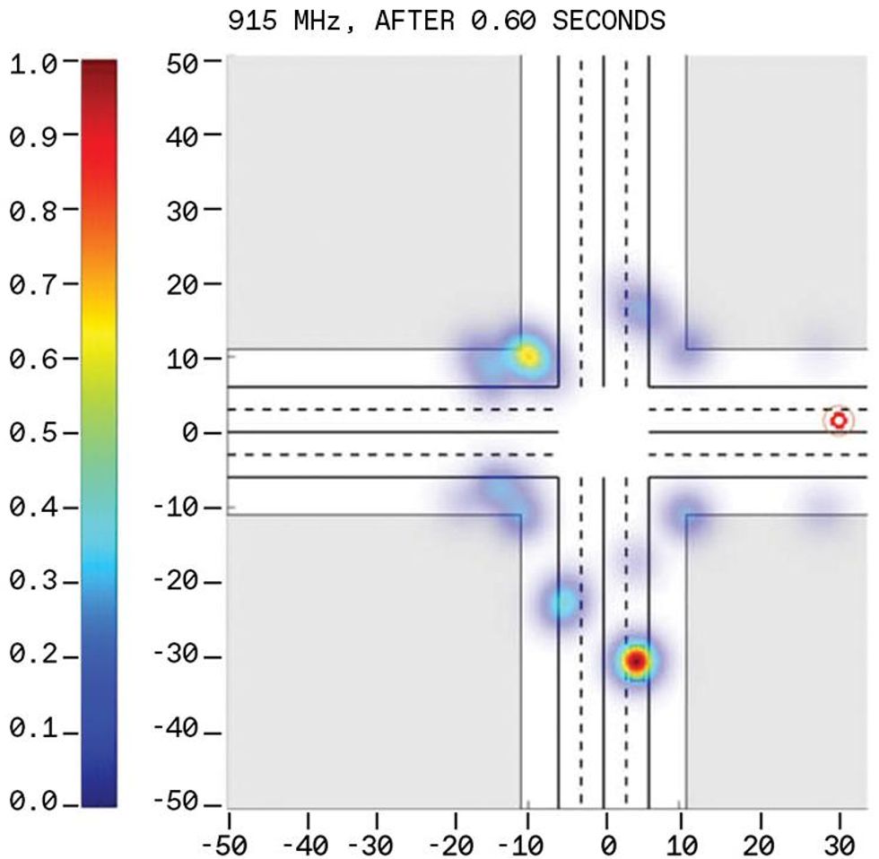
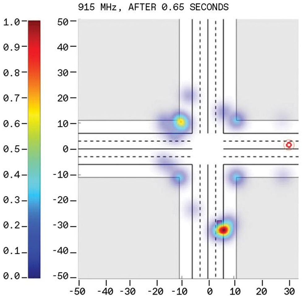
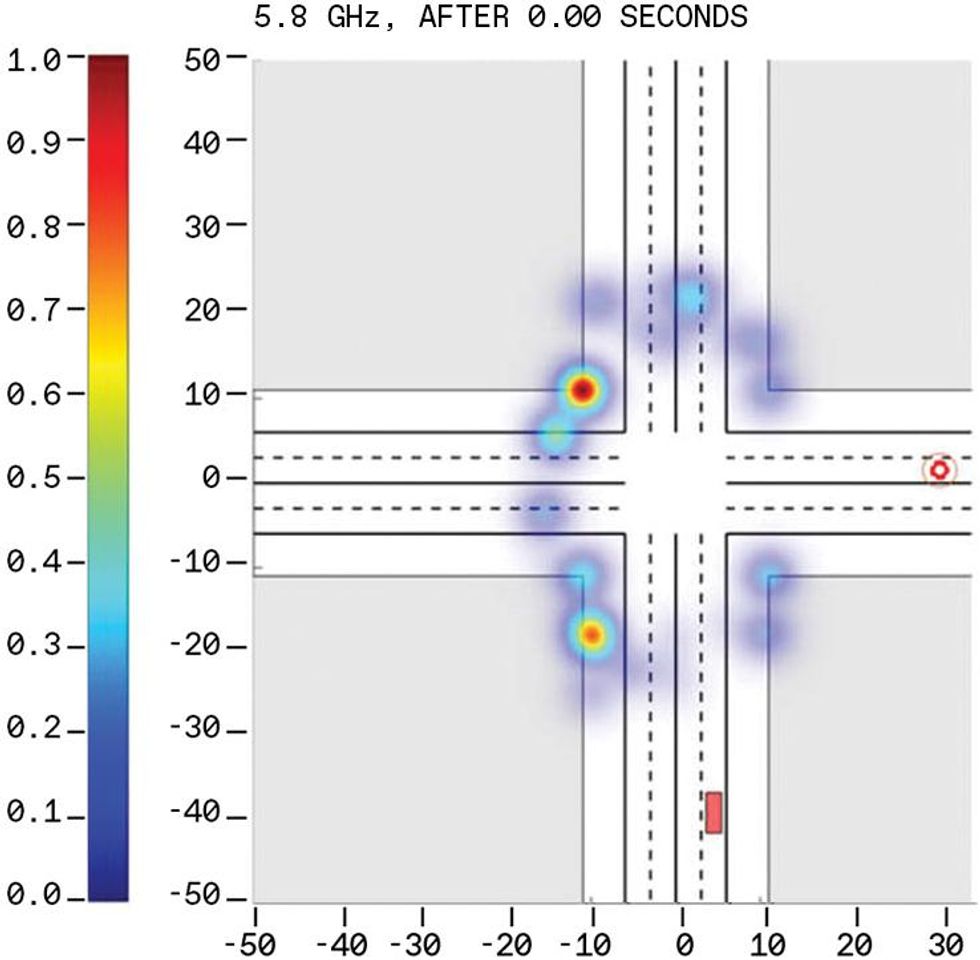
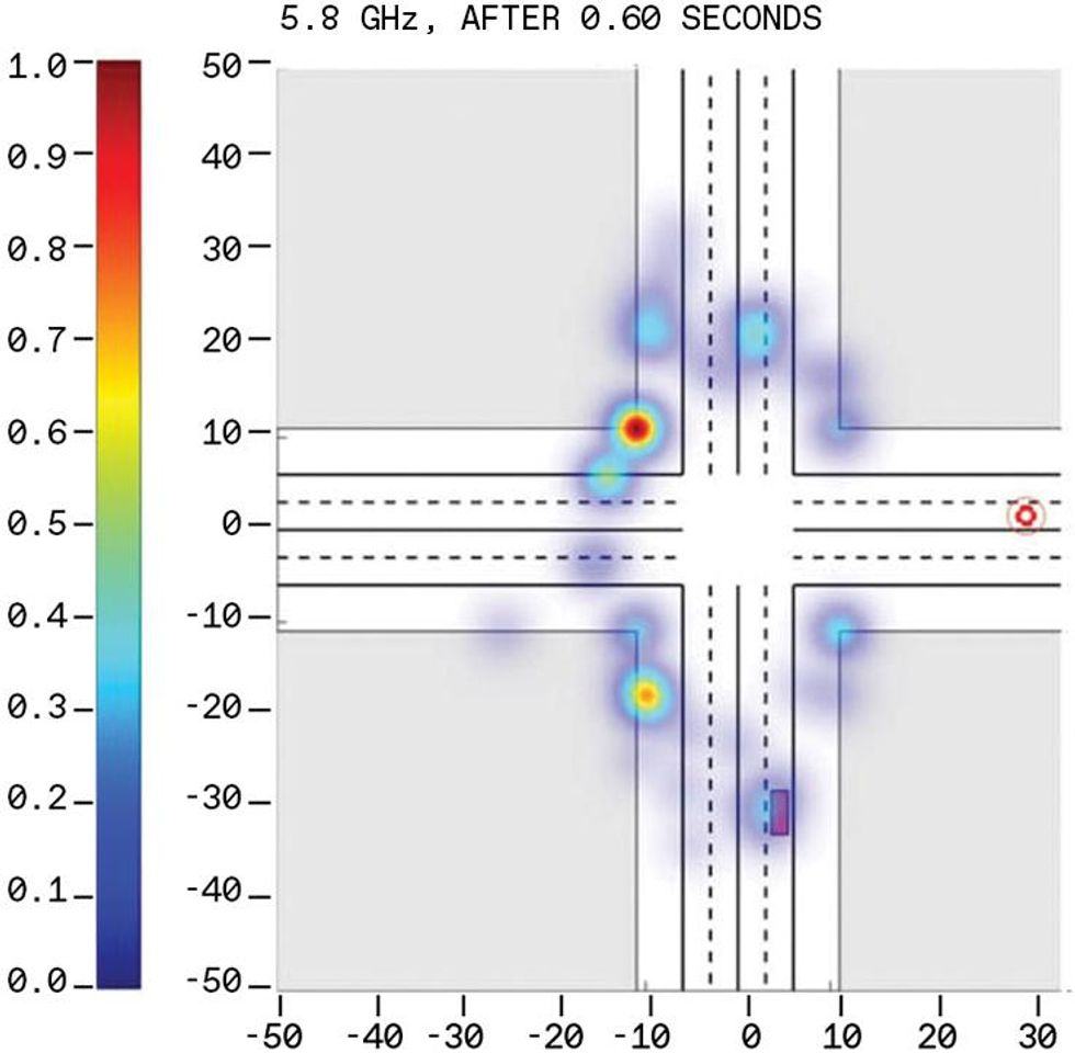
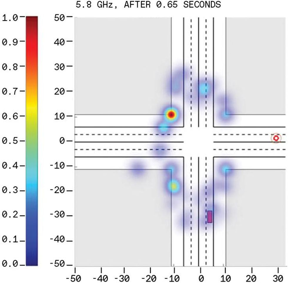
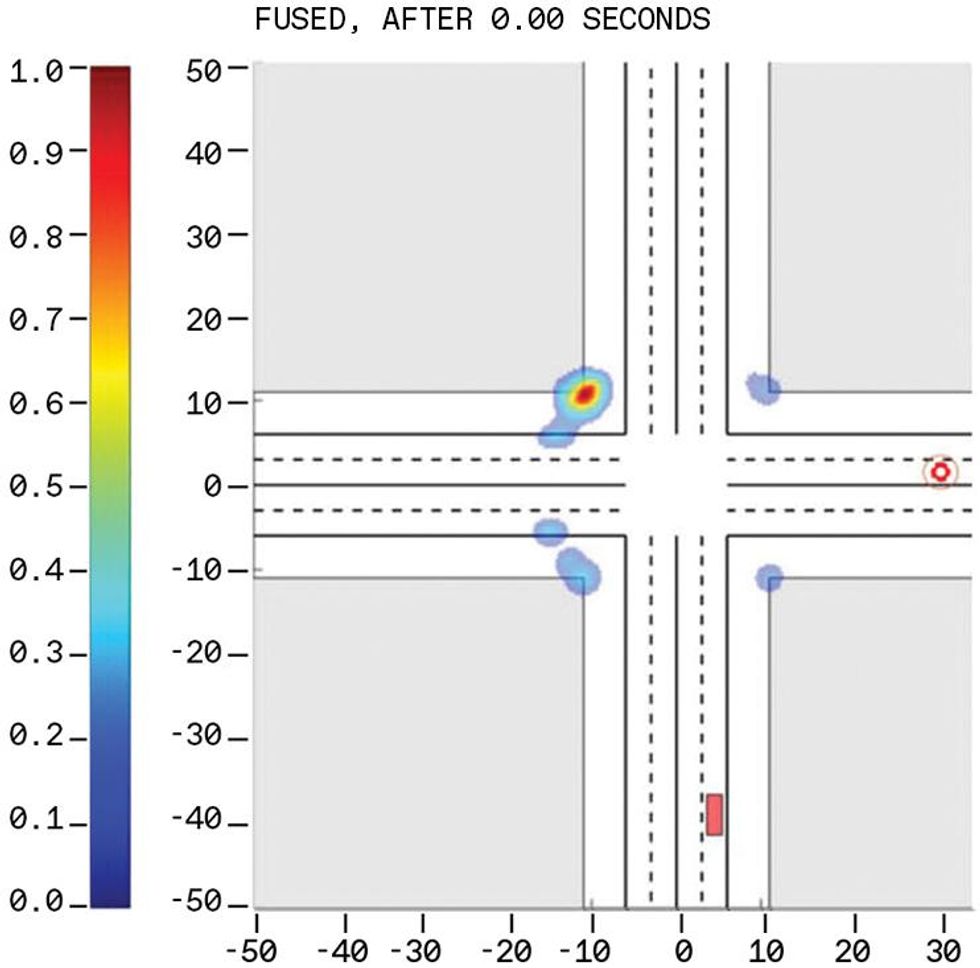
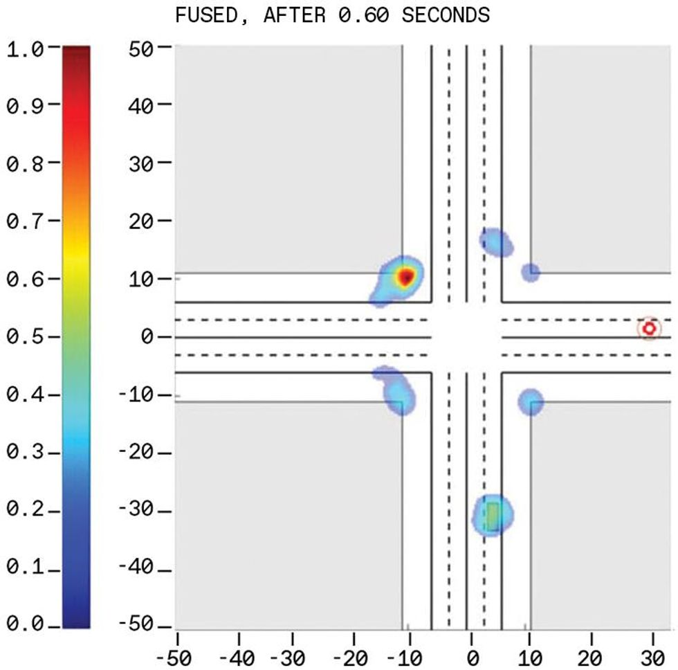
Seeing around the corner can be depicted easily in simulations. We considered an autonomous vehicle, equipped with our system, approaching an urban intersection with four high-rise concrete buildings, one at each corner. At the beginning of the simulation the vehicle is 35 meters from the center of the intersection and a second vehicle is approaching the center via a crossing road. The approaching vehicle is not within the autonomous vehicle's line of sight and so cannot be detected without a means of seeing around the corner.
At each of the three frequency bands, the radar system can estimate the range and bearing of the targets that are within the line of sight. In that case, the range of the target is equal to the speed of light multiplied by half the time it takes the transmitted electromagnetic wave to return to the radar. The bearing of a target is determined from the incident angle of the wavefronts received at the radar. But when the targets are not within the line of sight and the signals return along multiple routes, these methods cannot directly measure either the range or the position of the target.
We can, however, infer the range and position of targets. First we need to distinguish between line-of-sight, multipath, and through-the-building returns. For a given range, multipath returns are typically weaker (due to multiple reflections) and have different polarization. Through-the-building returns are also weaker. If we know the basic environment-the position of buildings and other stationary objects-we can construct a framework to find the possible positions of the true target. We then use that framework to estimate how likely it is that the target is at this or that position.
As the autonomous vehicle and the various targets move and as more data is collected by the radar, each new piece of evidence is used to update the probabilities. This is Bayesian logic, familiar from its use in medical diagnosis. Does the patient have a fever? If so, is there a rash? Here, each time the car's system updates the estimate, it narrows the range of possibilities until at last the true target positions are revealed and the ghost targets" vanish. The performance of the system can be significantly enhanced by fusing information obtained from multiple bands.
We have used experiments and numerical simulations to evaluate the theoretical performance limits of our radar system under various operating conditions. Road tests confirm that the radar can detect signals coming through occlusions. In the coming months we plan to demonstrate round-the-corner sensing.
The performance of our system in terms of range, angular resolution, and ability to see around a corner should be unprecedented. We expect it will enable a form of driving safer than we have ever known.