Maintaining Nuclear Plant Ice Condensers: A ‘Cool’ Responsibility
Although nuclear plant ice condensers are rare-only seven sites throughout the world have them-the theory behind these passive heat sinks is quite novel. In fact, some next-generation plant designers have built upon the concept and incorporated passive accident intervention schemes into their plans.
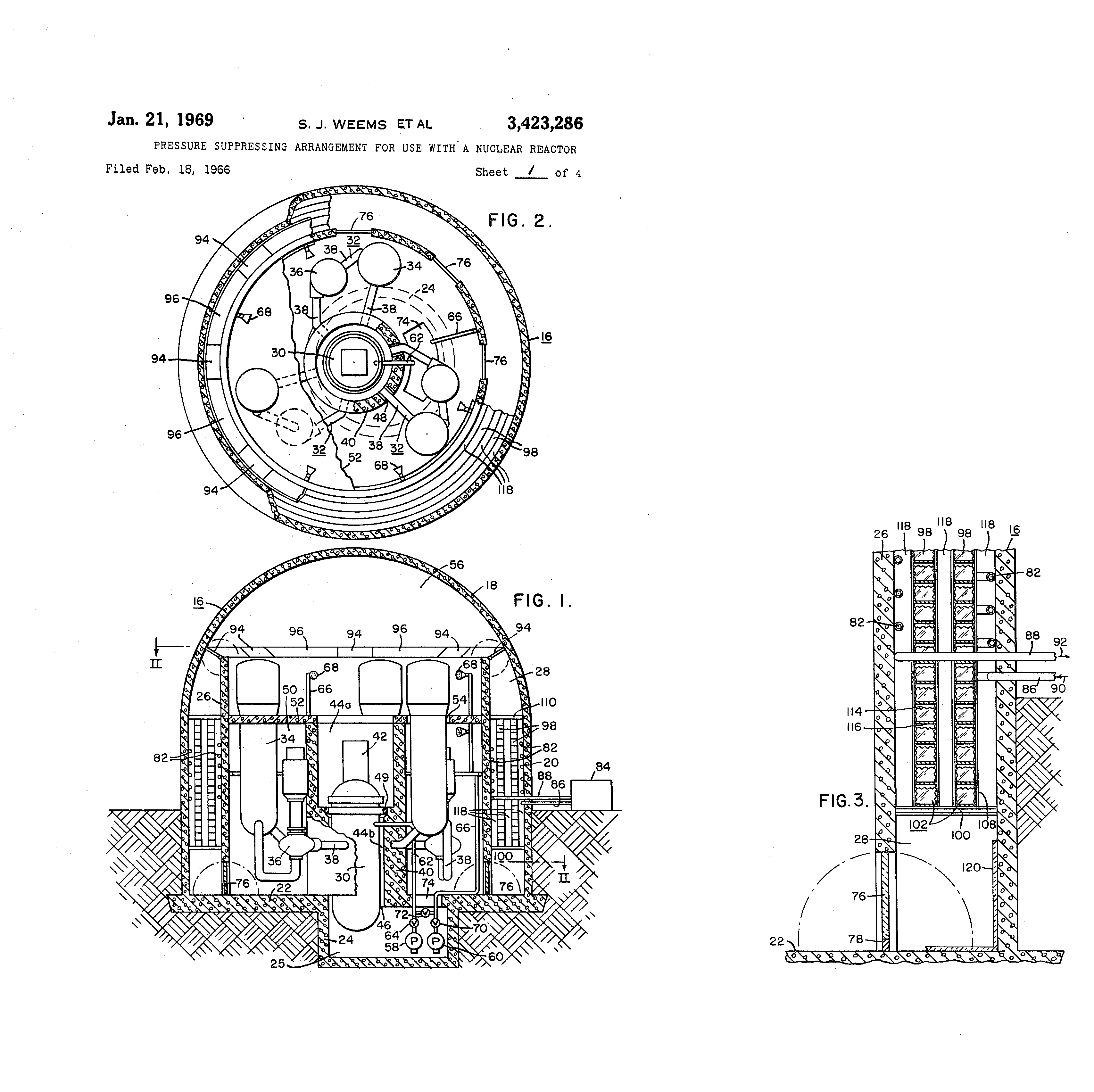
A nuclear plant ice condenser is a passive, static heat sink that relies on large quantities of ice to mitigate severe accidents. Its origin dates back to patent #3,423,286 filed in February 1966. It was called a "pressure suppressing arrangement for use with a nuclear reactor," and it allowed smaller containment structures and reduced material requirements. Of all the operating nuclear plants in the world, only Watts Bar 1 and 2, Sequoyah 1 and 2, Catawba 1 and 2, McGuire 1 and 2, D.C. Cook 1 and 2, Loviisa (Finland), and Ohi (Japan) rely on ice condenser systems.
This passive engineered safety feature (ESF) provides a static heat sink to rapidly absorb steam, reduce containment pressure and temperature, and remove fission products following a loss-of-coolant accident (LOCA) or main steam line break. The Nuclear Regulatory Commission defines a LOCA as "those postulated accidents that result in a loss of reactor coolant at a rate in excess of the capability of the reactor makeup system from breaks in the reactor coolant pressure boundary, up to and including a break equivalent in size to the double-ended rupture of the largest pipe of the reactor coolant system." Licensed nuclear plants must be capable of mitigating a LOCA and preventing offsite consequences.
POWER interviewed James Klein, maintenance FIN (fix-it-now) superintendent and ice condenser system subject matter expert at the Tennessee Valley Authority's (TVA's) Watts Bar nuclear plant located in southeastern Tennessee. The site has two Westinghouse four-loop, 1,150-MWe pressurized water reactors. Units 1 and 2 are licensed to operate until 2035 and 2055, respectively. (For more on the plant, see "Watts Bar Unit 2: A 'Deferred Nuclear Plant' Gets Back into the Game" in the June 2015 issue of POWER.) Klein discussed the major components of the ice condenser system, which are designed to manufacture ice and maintain a thermally controlled environment to keep the ice from melting.
Three Compartments and LOCA MitigationThe containment building is divided into three major compartments: a lower compartment consisting of the interior steel containment housing the reactor vessel and steam generators; the ice condenser compartment with one-way, hinged inlet (bottom) and outlet doors (top) that open upon slight pressure from the lower compartment and hinged vertically opening intermediate deck doors; and an upper compartment for displaced air from the other two compartments following a postulated LOCA. Return air fans maintain a forced circulation from the upper to lower compartments, equalizing containment pressure, and continuing to circulate heated air and steam through the ice condenser (Figure 1).
The ice condenser annular compartment is an enclosed low-temperature, static heat sink formed by the containment wall and a crane wall. Circumferentially, it covers a 300-degree perimeter of the upper containment structure. A refueling canal and equipment hatch are located in the remaining 60-degree arc. An operating deck separates the reactor vessel and upper compartment, with a portion of the ice condenser compartment extending into the lower compartment so the steam and heated air following a LOCA is directed through the lower inlet doors below the ice condensers.
For example, the lower inlet doors (92.5 inches high, 42 inches wide, and 7.5 inches thick) are located in crane wall ports. They are closed during normal operation, and equipped with torque-tension spring mechanisms, shock absorbers, and instrumented to verify their position. Following a pressure increase from a LOCA in the lower compartment, the doors open and vent the released energy into 24 ice condenser bays containing an array of 48-foot-long, vertical cylindrical columns of 1,944 twelve-inch-diameter perforated/lattice-mesh baskets that form flow channels.
The baskets contain flake ice impregnated with sodium tetraborate to mitigate the neutron fission/chain reaction and remove radioiodine. To assure that the iodine remains in solution, the alkaline pH (9.0-9.5) of the combined condensate and ice melt promotes iodine hydrolysis to non-volatile forms. Complete steam condensation occurs as it contacts the ice because of the ice mass and ice column geometrical arrangements. The resulting pressure rise, due principally to the air mass in the ice condensers, open the top outlet doors allowing airflow to vent into the upper compartment.
Accident analysis indicates that ice meltout occurs after approximately one hour. Drains at the bottom of 20 of the 24 ice condenser compartments allow melt/condensate water to flow out. Being a passive system, there are no actuation circuits or equipment required for the ice condensers to operate following a LOCA, and it is a part of several ESFs, such as the containment spray systems for reducing pressure, air return fans-which promote air flow and prevent the buildup of hazardous gas concentrations including hydrogen-and residual heat removal systems that cool recirculated water.
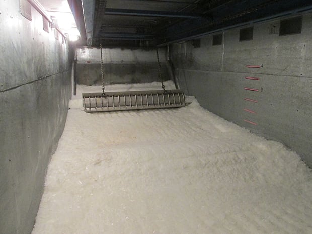
Nuclear IceThe ice is produced as a continuous ribbon, approximately one-eighth inch thick from machines located in the Additional Equipment Building. The ice is then deposited in storage bins via gravity chutes, pushed by a mechanized rake to an ice chopper sizing the ice flakes to approximately 2 in. x 2 in. x 1/8 in. (Figure 2).
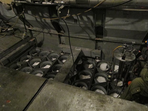
Change in ice basket weight determines how much ice has been lost, usually through sublimation, since the last outage. Although ice replacement is not a critical path item, approximately 2% to 4% of the ice is replenished every scheduled 18-month outage (Figures 3 and 4), thereby maintaining a technical specification (TS) requirement of 2,404,500 pounds of total ice weight per containment. Additional chillers were used to support the Watts Bar 2 startup.
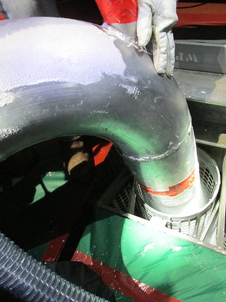 |
3. Blowing ice into an ice basket. Flake ice is being blown into one of the 1,944 baskets during preparations for Unit 2 operation. Courtesy: TVA/Watts Bar Nuclear Plant |
A three-stage refrigeration system-refrigerant loop, glycol loop, and air-cooling loop-cools the ice condensers and has defrost capability when needed. During normal operation, 30 air-handling units keep the ice beds at 15F to 20F. These conditions are maintained using a redundant, corrosion-inhibiting 50% glycol/water cooling system. Watts Bar has an average July temperature of 88F. Therefore, pipe coils are embedded in the ice condenser floors to minimize heat influx. Also, materials that could decompose and block water flow, such as solid insulation, is protected to prevent damage from LOCA blowdown effects.
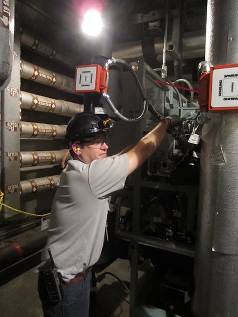
The insulation is sufficient to prevent ice melting for a minimum of seven days following a refrigeration system loss, allowing time for safe shutdown. Air-handling units located above the ice baskets provide cold forced-air through the ice systems. There are a number of sensors that monitor and provide feedback to the control room including indication for air temperature, ice condenser door position, glycol levels, glycol pump status, and glycol temperature (Figures 5 and 6).
An ice condenser systems engineer is responsible for the system. An operating engineering staff performs monitoring duties and a maintenance staff services the system. During full power operation, the upper compartment and ice condenser upper plenum areas are entered for ice bed and ice condenser inspection and maintenance, as required by the technical specification.
Routine ice condenser compartment checks verify that equipment performs within the prescribed limits. Items checked include:
- Ice condenser doors are not impaired by ice, frost, or debris, and have no evidence of damage.
- Air handling units, glycol circulation, and refrigeration equipment are functioning properly.
- Air temperature surrounding the ice condenser baskets is within specification.
- Quantity and quality of borated ice is correct.
- Gated floor drains and drain lines are free of debris.
- Gross inlet-outlet door bypass leakage paths between the upper and lower containments are not present.
Instrumentation failures or anomalies are monitored in the control room, where redundant ice condenser temperature monitors, door position monitors, coolant liquid level, and valve position indicators are displayed and alarmed. Ample time is available to investigate and eliminate off-normal conditions maintaining ice inventory and integrity.
Employee Safety and TrainingKlein said that because of the cold environment in the ice bays and their location inside the containment, pre-job safety and radiation worker permit briefings are conducted prior to entry. Workers use a "buddy system," and they are required to wear additional gear, such as coveralls, jackets, and gloves, for personal protection and comfort. Chemical protection and safety data sheets for glycol are reviewed when working on the chiller system.
Although the location is considered a radiologically low-dose and clean (that is, contamination-free) area, which eliminates the need for respirators, the health physics department requires wearing dosimeters to monitor for employee radiation exposure and contamination surveys are routinely conducted.
Respecting radiological dose implications, these containment access entries are limited to Tuesdays for Unit 1 and Thursdays for Unit 2. Refrigeration technicians conduct walkdowns, and if deficiencies are discovered, they are allowed to begin corrective maintenance processes. Klein added that maintenance has been proactive in monitoring for adverse trends in air-handling units and chiller performance, and conducts repairs, as needed.
Klein said training mainly focuses on refrigeration fundamentals. However, the individuals that perform maintenance must also have proper access and radiation safety qualifications to work onsite. Refrigeration training topics prescribed by the American Society of Heating, Refrigerating, and Air-Conditioning Engineers (ASHRAE) cover the following:
- Refrigeration and thermodynamics
- Refrigeration system components
- Refrigeration cycles
- Types of refrigerants and their characteristics
- Refrigeration system codes and standards
Ice condenser plants are unique among pressurized water reactors. This was the result of extensive development work during the early stages of the commercial nuclear industry as a part of a continuing effort to simplify nuclear plant designs, and reduce containment size and material usage, while improving safety using a passive system. This balance of proven technology and new concepts for accident intervention has been carried forward satisfying fundamental requirements demanded by the next generation of reactors.
-James M. Hylko(JHylko1@msn.com) specializes in safety, quality, and emergency management issues and is a frequent contributor to POWER.
The post Maintaining Nuclear Plant Ice Condensers: A 'Cool' Responsibility appeared first on POWER Magazine.
