Powering Offshore Wind Farms With Numerical Modeling of Subsea Cables
This sponsored article is brought to you by COMSOL.
Laws, Whitehouse received five minutes signal. Coil signals too weak to relay. Try drive slow and regular. I have put intermediate pulley. Reply by coils."
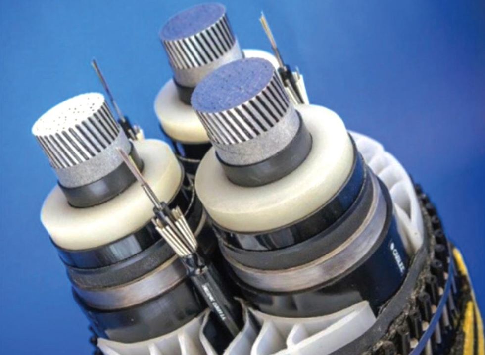
Sound familiar? The message above was sent through the first transatlantic telegraph cable between Newfoundland and Ireland, way back in 1858. (Whitehouse" refers to the chief electrician of the Atlantic Telegraph Company at the time, Wildman Whitehouse.) Fast forward to 2014: The bottom of the ocean is home to nearly 300 communications cables, connecting countries and providing internet communications around the world. Fast forward again: As of 2021, there are an estimated 1.3 million km of submarine cables (Figure 1) in service, ranging from a short 131 km cable between Ireland and the U.K. to the 20,000 km cable that connects Asia with North America and South America. We know what the world of submarine cables looks like today, but what about the future?

Moving Wind Power Offshore
The offshore wind (OFW) industry is one of the most rapidly advancing sources of power around the world. It makes sense: Wind is stronger and more consistent over the open ocean than it is on land. Some wind farms are capable of powering 500,000 homes or more. Currently, Europe leads the market, making up almost 80 percent of OFW capacity. However, the worldwide demand for energy is expected to increase by 20 percent in 10 years, with a large majority of that demand supplied by sustainable energy sources like wind power.
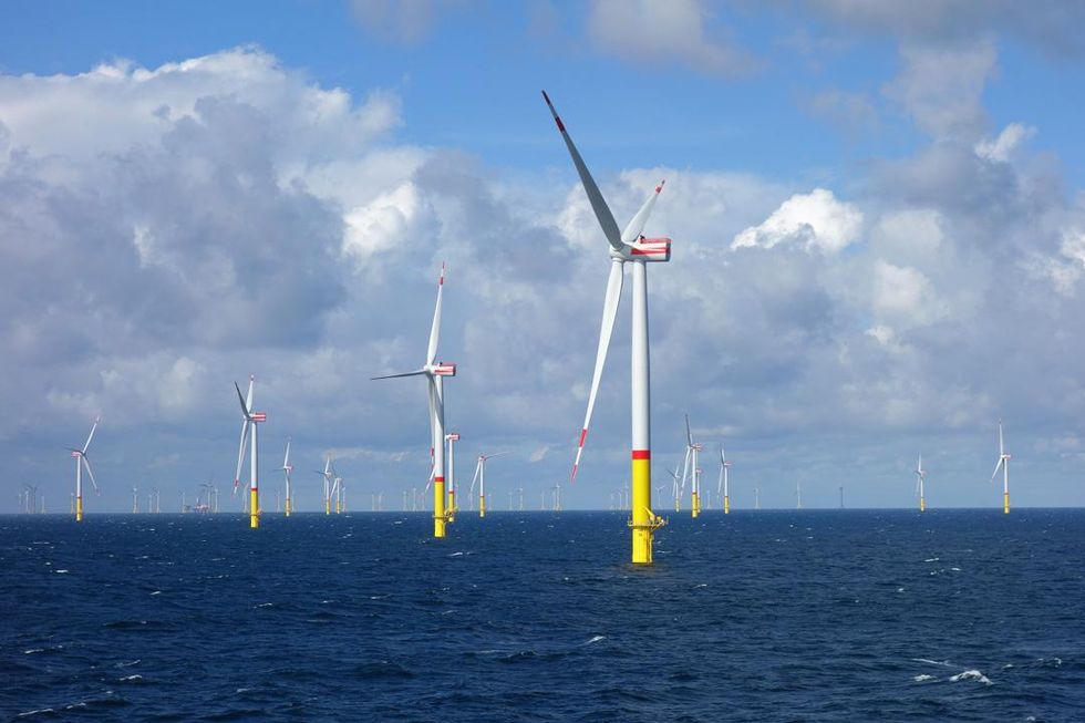
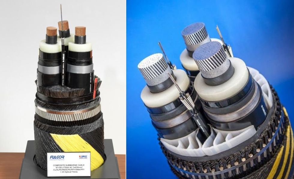
Offshore wind farms (Figure 2) are made up of networks of turbines. These networks include cables that connect wind farms to the shore and supply electricity to our power grid infrastructure (Figure 3). Many OFW farms are made up of grounded structures, like monopiles and other types of bottom-fixed wind turbines. The foundations for these structures are expensive to construct and difficult to install in deep sea environments, as the cables have to be buried in the seafloor. Installation and maintenance is easier to accomplish in shallow waters.
Wind turbines for offshore wind farms are starting to be built further out into the ocean. This creates a new need for well-designed subsea cables that can reach longer distances, survive in deeper waters, and better connect our world with sustainable power.
The future of offshore wind lies in wind farms that float on ballasts and moorings, with the cables laid directly on the seafloor. Floating wind farms are a great solution when wind farms situated just off the coast grow crowded. They can also take advantage of the bigger and more powerful winds that occur further out to sea. Floating wind farms are expected to grow more popular over the next decade. This is an especially attractive option for areas like the Pacific Coast of the United States and the Mediterranean, where the shores are deeper, as opposed to the shallow waters of the Atlantic Coast of the U.S., U.K., and Norway. One important requirement of floating OFW farms is the installation of dynamic, high-capacity submarine cables that are able to effectively harness and deliver the generated electricity to our shores.
Design Factors for Resilient Subsea Cables
Ever experienced slower than usual internet? Failure of a subsea cable may be to blame. Cable failures of this kind are a common - and expensive - occurrence, whether from the damage of mechanical stress and strain caused by bedrock, fishing trawlers, anchors, and problems with the cable design itself. As the offshore wind industry continues to grow, our need to develop power cables that can safely and efficiently connect these farms to our power grid grows as well.
Before fixing or installing a submarine cable, which can cost billions of dollars, cable designers have to ensure that designs will perform as intended in undersea conditions. Today, this is typically done with the help of computational electromagnetics modeling. To validate cable simulation results, international standards are used, but these standards have not been able to keep up with recent advancements in computational power and the simulation software's growing capabilities. Hellenic Cables, including its subsidiary FULGOR, use the finite element method (FEM) to analyze their cable designs and compare them to experimental measurements, often getting better results than what the international standards can offer.
Updated Methodology for Calculating Cable Losses
The International Electrotechnical Commission (IEC) provides standards for electrical cables, including Standard 60287 1-1 for calculating cable losses and current ratings. One problem with the formulation used in Standard 60287 is that it overestimates cable losses - especially the losses in the armor of three-core (3C) submarine cables. Cable designers are forced to adopt a new methodology for performing these analyses, and the team at Hellenic Cables recognizes this. With a more accurate and realistic model, significant optimization margins are expected," says Dimitrios Chatzipetros, team leader of the Numerical Analysis group at Hellenic Cables. The new methodology will enable engineers to reduce cable cross sections, thereby reducing their costs, which is the paramount goal for cable manufacturing.
An electric cable is a complex device to model. The geometric structure consists of three main power cores that are helically twisted with a particular lay length, and hundreds of additional wires - screen or armor wires - that are twisted with a second or third lay length. This makes it difficult to generate the mesh and solve for the electromagnetic fields. This is a tedious 3D problem with challenging material properties, because some of the elements are ferromagnetic," says Andreas Chrysochos, associate principal engineer in the R&D department of Hellenic Cables.
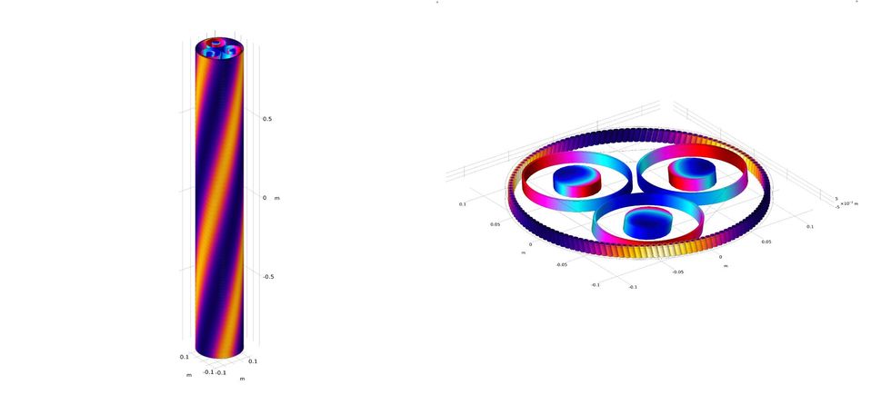
In recent years, FEM has made a giant leap when it comes to cable analysis. The Hellenic Cables team first used FEM to model a full cable section of around 30 to 40 meters in length. This turned out to be a huge numerical challenge that can only realistically be solved on a supercomputer. By switching to periodic models with a periodic length equal to the cable's cross pitch, the team reduced the problem from 40 meters down to 2-4 meters. Then they introduced short-twisted periodicity, which reduces the periodic length of the model from meters to centimeters, making it much lighter to solve. The progress was tremendous," says Chrysochos. (Figure 4)
Although the improvements that FEM brings to cable analysis are great, Hellenic Cables still needs to convince its clients that their validated results are more realistic than those provided by the current IEC standard. Clients are often already aware of the fact that IEC 60287 overestimates cable losses, but results visualization and comparison to actual measurements can build confidence in project stakeholders. (Figure 5)
Finite Element Modeling of Cable Systems
Electromagnetic interference (EMI) presents several challenges when it comes to designing cable systems - especially the capacitive and inductive couplings between cable conductors and sheaths. For one, when calculating current ratings, engineers need to account for power losses in the cable sheaths during normal operation. In addition, the overvoltages on cable sheaths need to be within acceptable limits to meet typical health and safety standards.
As Chrysochos et al. discuss in Capacitive and Inductive Coupling in Cable Systems - Comparative Study between Calculation Methods" (Ref. 3), there are three main approaches when it comes to calculating these capacitive and inductive couplings. The first is the complex impedance method (CIM), which calculates the cable system's currents and voltages while neglecting its capacitive currents. This method also assumes that the earth return path is represented by an equivalent conductor. Another common method is electromagnetic transients program (EMT) software, which can be used to analyze electromagnetic transients in power systems using both time- and frequency-domain models.
The third method, FEM, is the foundation of the COMSOL Multiphysics software. The Hellenic Cables team used COMSOL Multiphysics and the add-on AC/DC Module to compute the electric fields, currents, and potential distribution in conducting media. The AC/DC Module and solvers behind it are very robust and efficient for these types of problems," says Chrysochos.
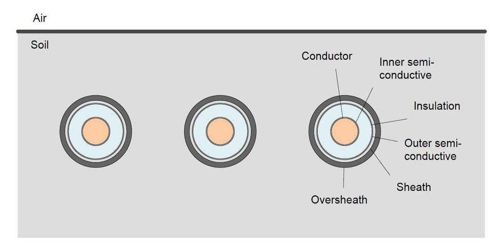
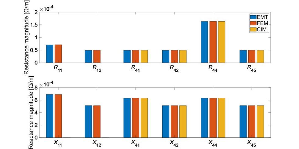
The Hellenic Cables team compared the three methods - CIM, EMT software, and FEM (with COMSOL Multiphysics) - when analyzing an underground cable system with an 87/150 kV nominal voltage and 1000 mm2 cross section (Figure 6). They modeled the magnetic field and induced current density distributions in and around the cable system's conductors, accounting for the bonding type with an external electrical circuit. The results between all three methods show good agreement for the cable system for three different configurations: solid bonding, single-point bonding, and cross bonding (Figure 7). This demonstrates that FEM can be applied to all types of cable configurations and installations when taking into account both capacitive and inductive coupling.
The Hellenic Cables team also used FEM to study thermal effects in subsea cables, such as HVAC submarine cables for offshore wind farms, as described in Review of the Accuracy of Single Core Equivalent Thermal Model for Offshore Wind Farm Cables" (Ref. 4). The current IEC Standard 60287 1-1 includes a thermal model, and the team used FEM to identify its weak spots and improve its accuracy. First, they validated the current IEC model with finite element analysis. They found that the current standards do not account for the thermal impact of the cable system's metallic screen materials, which means that the temperature can be underestimated by up to 8C. Deriving analytical, correcting formulas based on several FEM models, the team reduced this discrepancy to 1C! Their analysis also highlights significant discrepancies between the standard and the FEM model, especially when the corresponding sheath thickness is small, the sheath thermal conductivity is high, and the power core is large. This issue is particularly important for OFW projects, as the cables involved are expected to grow larger and larger.
Further Research into Cable DesignsIn addition to studying inductive and capacitive coupling and thermal effects, the Hellenic Cables team evaluated other aspects of cable system designs, including losses, thermal resistance of surrounding soil, and grounding resistance, using FEM and COMSOL Multiphysics. In general, COMSOL Multiphysics is much more user friendly and efficient, such as when introducing temperature-dependent losses in the cable, or when presenting semi-infinite soil and infinite element domains. We found several ways to verify what we already know about cables, their thermal performance, and loss calculation," says Chatzipetros.
LossesThe conductor size of a subsea or terrestrial cable affects the cost of the cable system. This is often a crucial aspect of an offshore wind farm project. To optimize the conductor size, designers need to be able to accurately determine the cable's losses. To do so, they first turned to temperature. Currents induced in a cable's magnetic sheaths yield extra losses, which contribute to the temperature rise of the conductor.
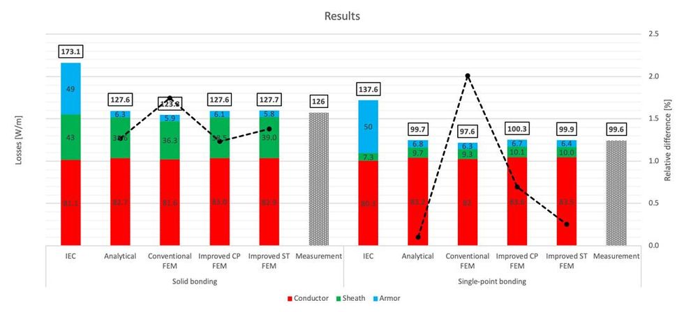
When calculating cable losses, the current IEC standard does not consider proximity effects in sheath losses. If cable cores are in close proximity (say, for a wind farm 3C cable), the accuracy of the loss calculation is reduced. Using FEM, the Hellenic Cables team was able to study how conductor proximity effects influence losses generated in sheaths in submarine cables with lead-sheathed cores and a nonmagnetic armor. They then compared the IEC standard with the results from the finite element analysis, which showed better agreement with measured values from an experimental setup (Figure 8). This research was discussed in the paper Induced Losses in Non-Magnetically Armoured HVAC Windfarm Export Cables" (Ref. 5).

Thermal Resistance of Soil
Different soil types have different thermal insulating characteristics, which can severely limit the amount of heat dissipated from the cable, thereby reducing its current-carrying capacity. This means that larger conductor sizes are needed to transmit the same amount of power in areas with more thermally adverse soil, causing the cable's cost to increase.
In the paper Rigorous calculation of external thermal resistance in non-uniform soils" (Ref. 6), the Hellenic Cables team used FEM to calculate the effective soil thermal resistance for different cable types and cable installation scenarios (Figure 9). First, they solved for the heat transfer problem under steady-state conditions with arbitrary temperatures at the cable and soil surfaces. They then evaluated the effective thermal resistance based on the heat dissipated by the cable surface into the surrounding soil.
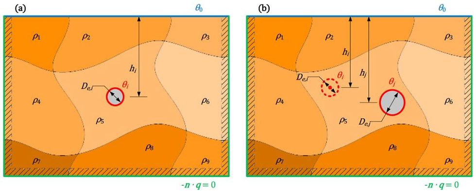
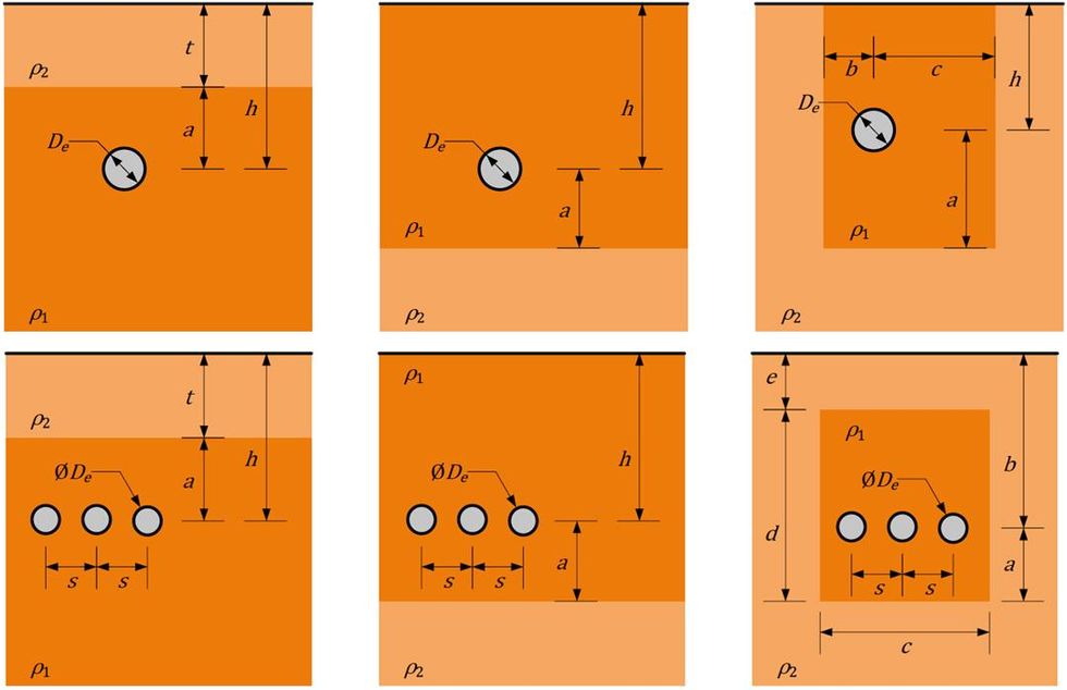
Simulations were performed for two types of cables: a typical SL-type submarine cable with 87/150 kV, a 1000 mm2 cross section, and copper conductors, as well as a typical terrestrial cable with 87/150 kV, a 1200 mm2 cross section, and aluminum conductors. The team analyzed three different cable installation scenarios (Figure 10).
The first scenario is when a cable is installed beneath a horizontal layer, such as when sand waves are expected to gradually add to the seafloor's initial level after installation. The second is when a cable is installed within a horizontal layer, which occurs when the installation takes place in a region with horizontal directional drilling (HDD). The third scenario is when a cable is installed within a backfilled trench, typical for regions with unfavorable thermal behavior, in order to reduce the impact of the soil on the temperature rise of the cable. The numerical modeling results prove that FEM can be applied to any material or shape of multilayer or backfilled soil, and that the method is compatible with the current rating methodology in IEC Standard 60287.
Grounding Resistance
The evaluation of grounding resistance is important to ensure the integrity and secure operation of cable sheath voltage limiters (SVLs) when subject to earth potential rise (EPR). In order to calculate grounding resistance, engineers need to know the soil resistivity for the problem at hand and have a robust calculation method, like FEM.
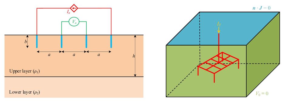
The Hellenic Cables team used FEM to analyze soil resistivity for two sites: one in northern Germany and one in southern Greece. As described in the paper Evaluation of Grounding Resistance and Its Effect on Underground Cable Systems" (Ref. 7), they found that the apparent resistivity of the soil is a monotonic function of distance, and that a two-layer soil model is sufficient for their modeling problem (Figure 11). After finding the resistivity, the team calculated the grounding resistance for a single-rod scenario (as a means of validation). After that, they proceeded with a complex grid, which is typical of cable joint pits found in OWFs. For both scenarios, they found the EPR at the substations and transition joint pit, as well as the maximum voltage between the cable sheath and local earth (Figure 12). The results demonstrate that FEM is a highly accurate calculation method for grounding resistance, as they show good agreement with both numerical data from measurements and electromagnetic transient software calculations (Figure 13).


A Bright and Windy Future
The Hellenic Cables team plans to continue the important work of further improving all of the cable models they have developed. The team has also performed research into HVDC cables, which involve XLPE insulation and voltage source converter (VSC) technology. HVDC cables can be more cost efficient for systems installed over long distances.
Like the wind used to power offshore wind farms, electrical cable systems are all around us. Even though we cannot always see them, they are working hard to ensure we have access to a high-powered and well-connected world. Optimizing the designs of subsea and terrestrial cables is an important part of building a sustainable future.
References- M. Hatlo, E. Olsen, R. Stolan, J. Karlstrand, Accurate analytic formula for calculation of losses in three-core submarine cables," Jicable, 2015.
- S. Sturm, A. Kuchler, J. Paulus, R. Stolan, F. Berger, 3D-FEM modelling of losses in armoured submarine power cables and comparison with measurements," CIGRE Session 48, 2020.
- A.I. Chrysochos et al., Capacitive and Inductive Coupling in Cable Systems - Comparative Study between Calculation Methods", 10th International Conference on Insulated Power Cables, Jicable, 2019.
- D. Chatzipetros and J.A. Pilgrim, Review of the Accuracy of Single Core Equivalent Thermal Model for Offshore Wind Farm Cables", IEEE Transactions on Power Delivery, Vol. 33, No. 4, pp. 1913-1921, 2018.
- D. Chatzipetros and J.A. Pilgrim, Induced Losses in Non-Magnetically Armoured HVAC Windfarm Export Cables", IEEE International Conference on High Voltage Engineering and Application (ICHVE), 2018.
- A.I. Chrysochos et al., Rigorous calculation of external thermal resistance in non-uniform soils", Cigre Session 48, 2020.
- A.I. Chrysochos et al., Evaluation of Grounding Resistance and Its Effect on Underground Cable Systems", Mediterranean Conference on Power Generation, Transmission , Distribution and Energy Conversion, 2020.